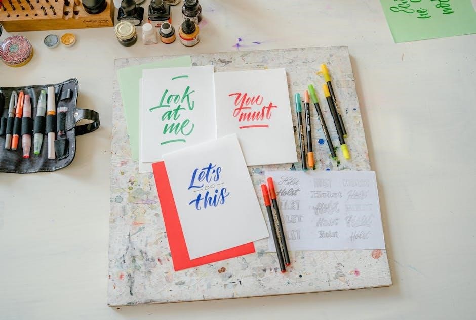
Drafting lettering is a fundamental aspect of technical drawing, ensuring clarity and precision in communication. Lettering guides are essential tools for creating uniform text, maintaining consistency, and enhancing legibility. They enable professionals to produce accurate and professional-looking drawings, which are critical for effective technical communication.
Importance of Lettering in Technical Drawings
Lettering plays a crucial role in technical drawings, as it ensures clarity and precision in communication. Legible and consistent text is essential for conveying dimensions, notes, and other critical information. Proper lettering helps maintain professionalism and accuracy, making drawings easier to interpret for engineers, architects, and other stakeholders.
In technical contexts, uniformity in lettering is vital. It prevents misunderstandings and ensures that all specifications are followed correctly. Guidelines and lettering guides, such as the Braddock and Ames tools, are used to achieve consistency in height, spacing, and alignment. This uniformity is particularly important in industries where precision is paramount, such as engineering and architecture.
Additionally, lettering contributes to the aesthetic quality of drawings. Well-executed text enhances the overall presentation, making it more professional and organized. Poor lettering, on the other hand, can lead to errors and misinterpretations, potentially causing delays or costly mistakes in projects. Therefore, mastering lettering techniques is a fundamental skill for anyone involved in technical drafting.
By adhering to established standards, such as the ASME Y14.2 guidelines, lettering ensures that technical drawings meet industry expectations. This consistency not only improves collaboration but also upholds the integrity of the design process. In summary, lettering is indispensable in technical drawings, serving as a bridge between creativity and functionality.
History and Evolution of Drafting Lettering
The history of drafting lettering dates back to the early days of technical drawing, where manual techniques dominated. Initially, lettering was done freehand, relying on the draftsman’s skill for consistency. The introduction of lettering guides in the mid-20th century revolutionized the process, enabling precise and uniform text in technical drawings.
The Braddock lettering guide, developed in the 1950s, became a cornerstone for drafters. It featured templates with letter cutouts, ensuring consistent height and spacing. This tool was soon complemented by the Ames lettering guide, which further refined alignment and spacing capabilities. Mechanical devices like the Leroy instrument also emerged, offering even greater accuracy for intricate lettering tasks.
The advent of CAD (Computer-Aided Design) in the 1980s marked a significant shift. Digital tools replaced manual methods, allowing for faster and more precise lettering. Despite this, traditional lettering guides remain popular for their tactile precision and artistic appeal. Today, drafters often combine both techniques, blending the efficiency of CAD with the craftsmanship of manual lettering.
Over time, lettering has evolved to meet the demands of modern technical communication. Standards like ASME Y14.2 have formalized best practices, ensuring consistency across industries. This rich history underscores the enduring importance of lettering in maintaining clarity and professionalism in technical documentation.
Role of Lettering in Technical Communication
Lettering plays a pivotal role in technical communication by ensuring clarity and accuracy in conveying information. In technical drawings, lettering is used to label components, specify dimensions, and provide critical instructions. Without proper lettering, even the most precise drawings can become ambiguous, leading to misunderstandings and potential errors.
One of the key functions of lettering is to maintain consistency across documents. Uniform letter height, spacing, and style help in creating a professional and readable format. This consistency is especially vital in industries like engineering and architecture, where precise communication is paramount. Additionally, lettering guides, such as the Braddock and Ames templates, ensure that text aligns perfectly with the overall design, enhancing the visual appeal and readability of technical documents;
Moreover, lettering serves as a bridge between the technical drawing and the viewer. It transforms complex designs into understandable information, facilitating effective collaboration among team members. By adhering to established standards, such as those outlined in the ASME Y14.2 guidelines, lettering contributes to the overall effectiveness of technical communication, ensuring that information is conveyed accurately and efficiently.

Tools and Instruments for Drafting Lettering
Drafting lettering relies on essential tools like the Braddock Lettering Guide, Ames Lettering Guide, and Leroy Instrument. These instruments, along with additional accessories, ensure accurate and consistent text alignment, crucial for professional technical drawings and documentation.
Braddock Lettering Guide: Features and Usage
The Braddock Lettering Guide is an indispensable tool for achieving precise and uniform lettering in technical drawings. It features three columns of holes, each spaced at 1/32-inch increments, designed to guide letter height consistency. The center column is used to align the baseline of letters, while the left and right columns help in maintaining uniformity in the top edges of characters. This tool is particularly useful for creating clear and legible text, essential for professional documentation.
To use the Braddock Lettering Guide, align it with a T-square to ensure straight guidelines. Place the guide on the drawing surface and lightly draw the baseline and top edges using a pencil. This setup allows drafters to letter consistently, with each letter maintaining the same height and spacing. The guide also accommodates various lettering styles, making it versatile for different projects.

By providing precise control over lettering alignment and spacing, the Braddock Lettering Guide enhances the clarity and professionalism of technical drawings. Its durability and ease of use make it a preferred choice among architects, engineers, and drafters. Regular practice with this tool helps improve lettering accuracy and speed, ensuring high-quality results in every project.
Ames Lettering Guide: Adjusting and Aligning

The Ames Lettering Guide is a versatile tool designed to facilitate precise and consistent lettering in technical drawings. Its adjustable features allow users to customize letter spacing and alignment according to specific project requirements. The guide consists of a disk with numbered settings, which determine the spacing between guidelines in 1/32-inch increments.
To use the Ames Lettering Guide, drafters rotate the disk to select the desired spacing. Once set, the guide can be aligned with a T-square to draw horizontal or inclined lines. The center column of holes ensures uniform vertical spacing, while the outer columns provide alignment for the top edges of letters. This setup helps maintain consistency in letter height and spacing, crucial for readability.
The tool’s simplicity and precision make it ideal for both beginners and professionals. By adjusting the spacing settings and aligning the guide accurately, users can achieve professional-quality lettering efficiently. Regular use of the Ames Lettering Guide enhances drafting skills, ensuring that all text in technical drawings is clear, legible, and uniformly formatted.
Mechanical Lettering Devices: Leroy Instrument
The Leroy lettering instrument is a mechanical device designed to produce precise and consistent lettering on technical drawings. It uses interchangeable templates with cutouts for letters, numbers, and symbols, guiding a stylus to create accurate characters. This tool was widely used in drafting before the advent of CAD software.
To use the Leroy instrument, drafters select the appropriate template based on the required character set. The stylus is then traced along the edges of the template, ensuring uniform lettering. The instrument is particularly effective for creating intricate details and maintaining consistency in complex drawings.
While the Leroy instrument has largely been replaced by digital tools, it remains a significant part of drafting history. Its precision and ability to handle detailed work made it indispensable in traditional drafting practices. However, its mechanical nature required skill and patience, limiting its efficiency compared to modern CAD solutions.
Despite its decline in use, the Leroy instrument highlights the evolution of drafting tools, showcasing how mechanical devices laid the groundwork for the advanced software used today. It continues to be recognized for its role in maintaining high standards of lettering quality in technical drawings.
Additional Accessories for Lettering Precision
Beyond primary tools like lettering guides, several accessories enhance precision and efficiency in drafting lettering. T-squares, for instance, are often used alongside lettering guides to ensure proper alignment and straight lines. They help maintain consistent heights and spacing between rows of text.
Light boxes or illuminated drafting boards are another valuable accessory. They allow drafters to trace guidelines or templates with greater accuracy, reducing errors and improving overall legibility. Additionally, adjustable pencil sharpeners and specific grades of pencils, such as H or 2H, are essential for creating fine, consistent lines.
Guideline templates with pre-drawn spacing and character alignment marks are also widely used. These templates help maintain uniformity in lettering, especially in complex drawings. Furthermore, masking tape can be used to secure paper or templates in place, preventing movement during the lettering process.

These accessories collectively contribute to achieving professional-grade lettering in technical drawings. They not only save time but also ensure that the final output meets the high standards required for clarity and precision in engineering and architectural documentation.

Techniques and Best Practices
Effective drafting lettering requires precision and consistency. Key techniques include setting up guidelines, maintaining uniform letter height and spacing, and ensuring legibility. Using tools like T-squares and lettering guides helps achieve alignment and accuracy. Practice and patience are essential for mastering these skills.
- Use guidelines to maintain consistent letter height and spacing.
- Ensure letters are legible and aligned properly.
- Employ T-squares for precise alignment.
Setting Up Guidelines for Consistency
Setting up guidelines is a critical step in ensuring consistency in drafting lettering. These guidelines help maintain uniform letter height, spacing, and alignment, which are essential for legibility and professionalism in technical drawings. To set up guidelines effectively, use a T-square to draw light, precise lines that serve as a reference for lettering. These lines should be spaced evenly, typically 1/8 inch apart, to accommodate standard letter heights and spacing. For added accuracy, lettering guides like the Braddock or Ames guides can be used to create consistent lettering templates. Properly aligned guidelines ensure that all text maintains a uniform appearance, making the drawing easier to read and understand. Consistent guidelines also help in maintaining the overall aesthetic and functional quality of the drawing. By following these practices, drafters can achieve precise and professional-looking lettering in their work.
Maintaining Uniform Letter Height and Spacing
Maintaining uniform letter height and spacing is vital for ensuring clarity and professionalism in technical drawings. Uniformity in lettering prevents misinterpretation and enhances readability, making it easier for viewers to understand the information conveyed. To achieve consistent letter height, guidelines should be set using tools like T-squares or lettering guides, ensuring that all letters align to the same baseline. The height of letters typically ranges between 1/8 inch to 1/4 inch, depending on the scale of the drawing. Spacing between letters should be proportional to their height, with a general rule of maintaining a space of 1/16 inch between letters to avoid overcrowding. Additionally, spacing between words should be at least twice the spacing between letters to ensure clear separation. Using lettering guides, such as the Braddock or Ames guides, can help maintain these standards by providing predefined templates for consistent lettering. Regular practice and attention to detail are essential for mastering the skill of uniform letter height and spacing, which are fundamental to effective technical communication.
Ensuring Legibility in Lettering
Ensuring legibility in lettering is crucial for effective technical communication. Clear and readable text prevents misinterpretation of critical information in drawings. Legibility is influenced by factors such as letter height, spacing, and line weight. Letters should be sufficiently large to be easily visible, typically ranging in height from 1/8 inch to 1/4 inch, depending on the drawing’s scale. Proper spacing between letters and words is equally important, as overcrowding can reduce clarity. Using uppercase letters exclusively, except in specific cases like lengthy descriptions, helps maintain uniformity and readability. Additionally, guidelines should be used to align letters consistently, eliminating slanting or uneven text. Tools like lettering guides and mechanical devices, such as the Leroy instrument, aid in producing precise and legible lettering. Avoiding excessive ornamentation and ensuring high contrast between the lettering and the drawing background further enhance legibility. Regular practice and adherence to established standards, such as those outlined in the ASME Y14.2 guidelines, are essential for mastering legible lettering. By focusing on these principles, drafters can ensure that their lettering is clear, professional, and easily understandable.
Using T-Squares for Alignment
The T-square is a versatile tool essential for maintaining precise alignment in drafting lettering. Its straightedge ensures that guidelines are drawn accurately, helping to keep lettering consistent and evenly spaced. By aligning the T-square with the drawing’s reference lines, drafters can create horizontal or vertical baselines for text, preventing slanted or uneven letters. This tool is particularly useful for setting up uniform letter heights and spacing, which are critical for legibility. Proper use involves securing the T-square firmly against a drawing board or other stable surface, ensuring it remains steady while drawing guidelines. Regularly checking the T-square’s alignment with other drafting tools, such as triangles, helps maintain overall accuracy. For intricate layouts, combining the T-square with lettering guides enhances precision, allowing for refined control over text placement. Mastery of the T-square is a fundamental skill for drafters, as it directly impacts the professionalism and clarity of the final drawing. By leveraging the T-square’s precision, drafters can ensure their lettering aligns seamlessly with the rest of the drawing, contributing to a polished and professional outcome.

CAD Lettering Styles

CAD lettering styles streamline text creation in technical drawings, enabling standardized fonts and sizes. They enhance productivity by allowing pre-defined styles, ensuring consistency across projects. CAD tools support customization, scalability, and adherence to industry standards like ASME Y14.2, making lettering precise and efficient.
Creating and Managing Lettering Styles
Creating and managing lettering styles in CAD involves defining font types, sizes, and other attributes to ensure consistency. Users can customize styles to meet specific project requirements, storing them for reuse across multiple drawings. This feature enhances efficiency by eliminating repetitive setup. Managing styles also involves updating or modifying existing ones to adapt to new standards or project needs. Proper organization of styles ensures that all team members follow the same guidelines, maintaining uniformity in technical documentation. Additionally, CAD software allows for easy duplication and adjustment of styles, making it simpler to maintain a standardized approach. By leveraging these tools, professionals can focus on design and communication without compromising on clarity and precision.
ASME Y14.2 Standard for Lettering
The ASME Y14.2 standard provides guidelines for lettering in technical documentation, ensuring clarity and consistency. It specifies that all lettering should be in uppercase, with exceptions for abbreviations like “ASME.” The standard recommends sans-serif fonts for better readability. Letter height should be a minimum of 0.094 inches, with spacing between letters and lines adhering to precise measurements to avoid overcrowding. Line weights for lettering should be 0.01 inches to maintain uniformity. These standards ensure that technical drawings are easily interpretable by professionals across industries. By following ASME Y14.2, drafters can produce documents that meet industry expectations and facilitate effective communication. Proper adherence to these guidelines is essential for maintaining professionalism and accuracy in technical documentation.
Advantages of CAD in Lettering
CAD (Computer-Aided Design) revolutionizes lettering in drafting by offering unparalleled efficiency and precision. One key advantage is the ability to create and manage standardized lettering styles effortlessly, ensuring consistency across projects. CAD software allows for quick adjustments in font, size, and spacing, eliminating the need for manual adjustments. Additionally, CAD enables the creation of complex scripts and annotations with ease, reducing the time spent on repetitive tasks. The software also supports multi-user collaboration, making it easier to maintain uniformity in large-scale projects. Furthermore, CAD tools minimize errors associated with manual lettering, such as inconsistent spacing or incorrect alignment. The ability to store and reuse lettering styles streamlines the drafting process. Overall, CAD enhances productivity, accuracy, and creativity in lettering for technical drawings, making it an indispensable tool in modern drafting practices.
Drafting lettering guides are essential for creating clear, consistent, and professional technical drawings. By combining traditional tools like lettering guides with modern CAD techniques, drafters can ensure precision and efficiency in communication, making lettering a cornerstone of effective technical documentation and collaboration.

Key Considerations for Effective Lettering
Effective lettering in technical drawings requires careful attention to detail and adherence to established standards. Consistency is paramount, ensuring that all text maintains uniform height, spacing, and style throughout the drawing. Legibility is equally critical, as unclear lettering can lead to misinterpretation of dimensions and specifications.
The use of lettering guides, such as the Braddock or Ames templates, is highly recommended to achieve uniformity. These tools help maintain consistent letter height and spacing, reducing the risk of human error. Additionally, guidelines should always be drawn before lettering to ensure proper alignment and spacing.
Lettering should be executed with precision, avoiding slanting or unevenness. T-squares and other alignment tools can assist in maintaining straight lines, especially for horizontal text. Proper line weight and pencil selection are also important, with H or 2H pencils being ideal for crisp, clear strokes.
Ultimately, effective lettering enhances the professionalism and clarity of technical drawings, making it easier for stakeholders to understand and implement the designs. By following these key considerations, drafters can ensure their work is both accurate and visually appealing.

Future of Drafting Lettering: Tradition vs. Innovation
The future of drafting lettering lies in the balance between tradition and innovation. Traditional tools like lettering guides have long been the backbone of precise and consistent text in technical drawings, offering reliability and a tactile experience. However, advancements in CAD software are revolutionizing the field, enabling faster and more customizable lettering styles while maintaining adherence to standards like ASME Y14.2.
CAD programs allow for the creation of reusable lettering styles, reducing errors and enhancing efficiency. Yet, many professionals still value traditional methods for their hands-on control and artistic appeal. The integration of both approaches could redefine drafting practices, blending the accuracy of digital tools with the craftsmanship of manual techniques.
As technology evolves, the emphasis will likely shift toward hybrid workflows, where drafters can seamlessly transition between physical guides and software. This fusion ensures that the principles of clear and legible lettering are upheld while embracing modern advancements. The future of drafting lettering is poised to be a dynamic interplay of tradition and innovation, catering to diverse needs across industries.